Driving a DC Motor with a Raspberry Pi and an L298N Dual H-Bridge
· 5 min read · raspberry pi, l298n, h-bridge, dc motor, python
The Curiosity rover I was building needed larger motors than the 1-inch cans you find in RC toys, and the Adafruit Motor HAT I'd used on the Pi car couldn't feed them. I either exceeded its current rating or I blew the boards; a decade later I honestly don't remember which, and it doesn't matter, because the answer in both cases is the same: a bare H-bridge with its own power input.
This is the wiring and the minimum script to make one motor spin both ways. Skip the introduction if you just want it connected.
The board
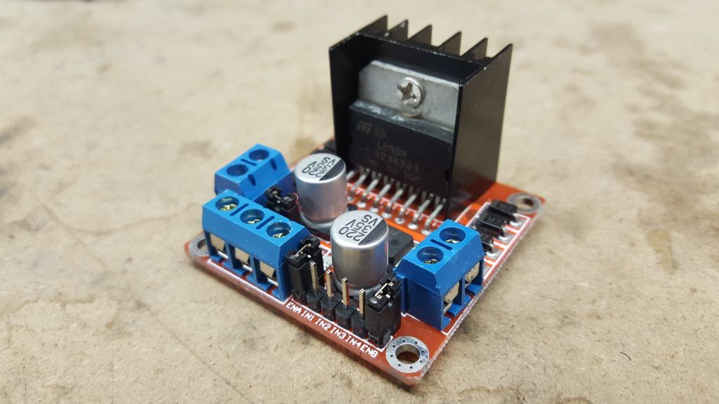
A generic L298N dual H-bridge module. The numbers that matter:
- Logic voltage: 5 V
- Motor voltage: 5–35 V
- Drive current: 2 A per bridge, max
- Max power: 25 W
Two motors per board, one per bridge.
The two jumpers nobody explains
The 5 V regulator jumper. With it in place, the board makes its own logic 5 V from the motor supply. If your motor supply is 12 V or under, leave it in and don't wire the +5 V terminal at all. Above 12 V, pull it and feed 5 V separately, or you'll cook the regulator.
The ENA / ENB jumpers. Each one holds a bridge's enable pin high, meaning "run whenever an IN pin is high, at full speed." Leave them in if you don't care about speed. Pull them if you want PWM control, then drive the enable pin from the Pi yourself. More on that at the end.
Wiring
I'm on a 6 V battery, so the regulator jumper stays in. Battery positive to the left power terminal, negative to the middle GND terminal. I use terminal blocks because these projects sprout wires.
Two signal wires from IN1 and IN2 to the Pi. I use physical pins 16 and 18, which are GPIO23 and GPIO24 in the other numbering. Everything below uses physical numbering; if you see "GPIO23" elsewhere, it's the same pin.
Motor leads to the Motor A screw terminals. Polarity doesn't matter here. That's the whole point of an H-bridge: whichever IN pin is high decides the direction.
Ground the Pi and the driver together. If you skip this, the motor twitches or does nothing and you'll spend an hour blaming the code.
The script
Assuming Python and RPi.GPIO are installed (sudo apt-get install python-dev python-rpi.gpio in 2016; today RPi.GPIO ships with Raspberry Pi OS):
import time
import RPi.GPIO as GPIO

# Physical board numbering, not BCM
GPIO.setmode(GPIO.BOARD)

IN1 = 16
IN2 = 18

GPIO.setup(IN1, GPIO.OUT)
GPIO.setup(IN2, GPIO.OUT)

print("Motor A, direction one")
GPIO.output(IN1, GPIO.HIGH)
time.sleep(2)
GPIO.output(IN1, GPIO.LOW)

print("Motor A, direction two")
GPIO.output(IN2, GPIO.HIGH)
time.sleep(2)
GPIO.output(IN2, GPIO.LOW)

GPIO.cleanup()
GPIO.setup only configures the pins; nothing moves until GPIO.output goes high. Run it with sudo python3 motor.py. Two seconds one way, two seconds the other.
Never set IN1 and IN2 high at the same time. The chip tolerates it (both sides of the bridge pulled the same way, so the motor brakes), but it's the state you'll get by accident when a script crashes mid-run, which is why the cleanup() line is not optional.
The PWM tutorial I promised in 2016
Pull the ENA jumper and run a third wire from ENA to physical pin 12 (GPIO18, one of the hardware PWM pins). Then:
ENA = 12
GPIO.setup(ENA, GPIO.OUT)
speed = GPIO.PWM(ENA, 1000)   # 1 kHz
speed.start(0)

GPIO.output(IN1, GPIO.HIGH)
for duty in (30, 60, 100):
    speed.ChangeDutyCycle(duty)
    time.sleep(2)

speed.stop()
GPIO.cleanup()
Duty cycle is percent. Below about 25–30 % a brushed motor under load just hums, so clamp your minimum there instead of at zero.
What I'd tell 2016 me
The L298N eats two volts. It's a bipolar chip, and it drops roughly 1.5–2 V across the bridge at load. On my 6 V pack the motors were seeing about 4 V. That's a big part of why the "larger" motors still felt weak. If you're starting today, a TB6612FNG or a DRV8871 board costs the same, drops a fraction of a volt, and doesn't need a heatsink.
Physical pin numbering was the right call for a wiring tutorial and the wrong call for code. Everything else in the ecosystem uses BCM. Pick BCM, put a comment with the physical pin next to it.
Python 2 print statements. The original had them. I've fixed them above.
Where it is now
September 2026. The rover this driver was built for is gone; it got trashed somewhere between two moves. The L298N approach outlived it, though. It's still the board I'd reach for to prove a motor spins before I bother with anything nicer. Ten years on, this is still the post on my old blog that people arrive at from Stack Exchange, which is why it's here unchanged in substance.